Basic 3D Viewer
3D viewer provides a rich experience with multiple useful tools for working with the assembly.
It allows you to:
- View the assembly from different angles by freely moving/rotating it;
- Have a holistic view of the whole project and what role your assembly plays within it;
- Conceptualize your build from 2D to 3D and see how it actually looks in different dimensions.
Please use 3D viewer measuring tool is for reference only. Always pull 2 different dimensions for the reference point to make sure they correspond.
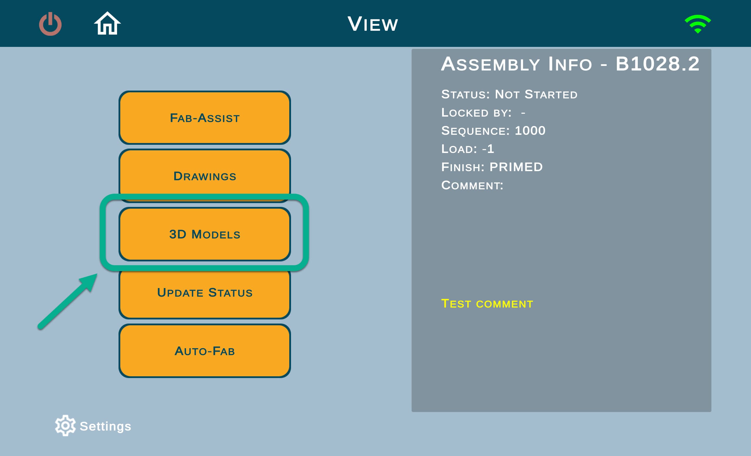
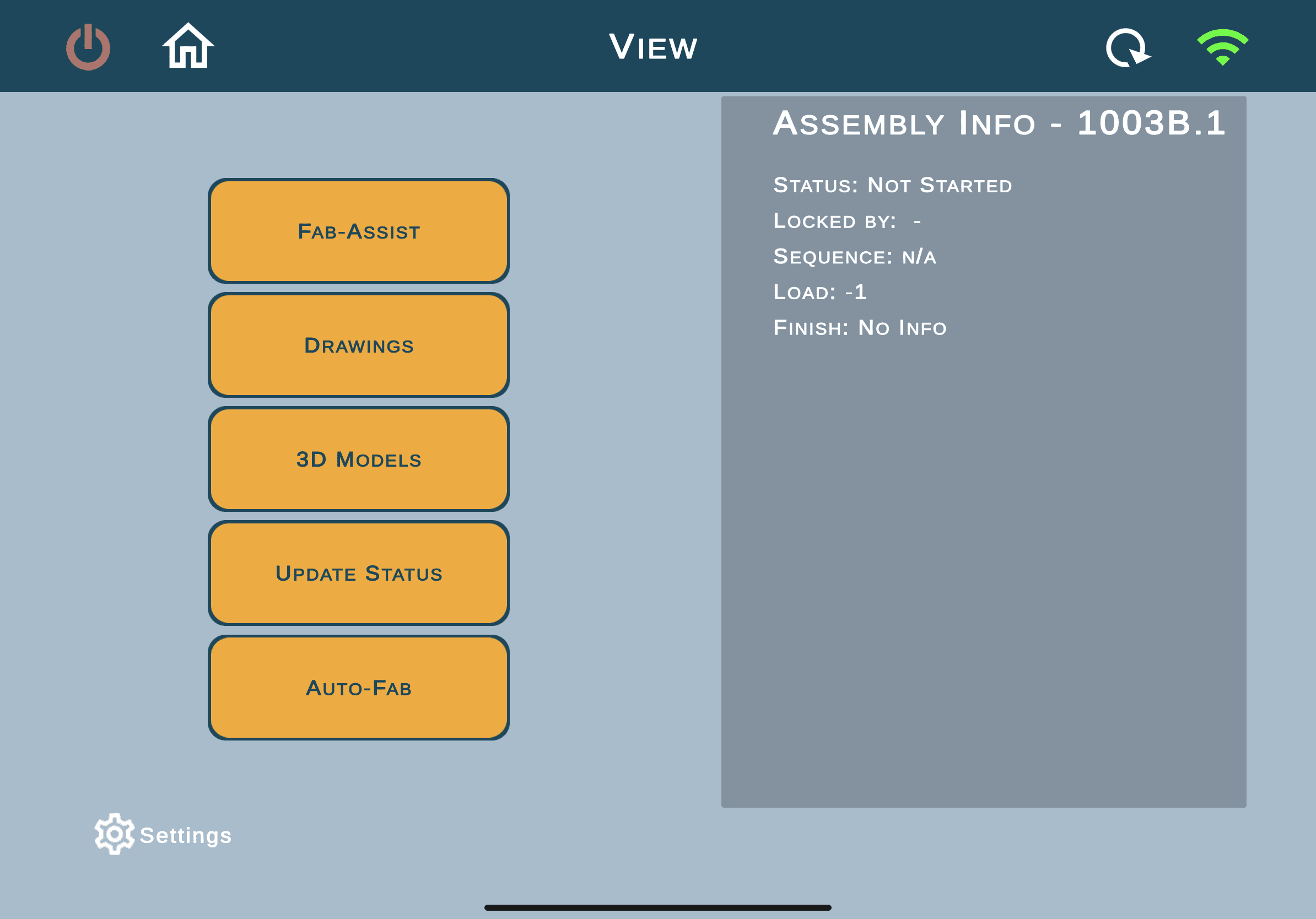
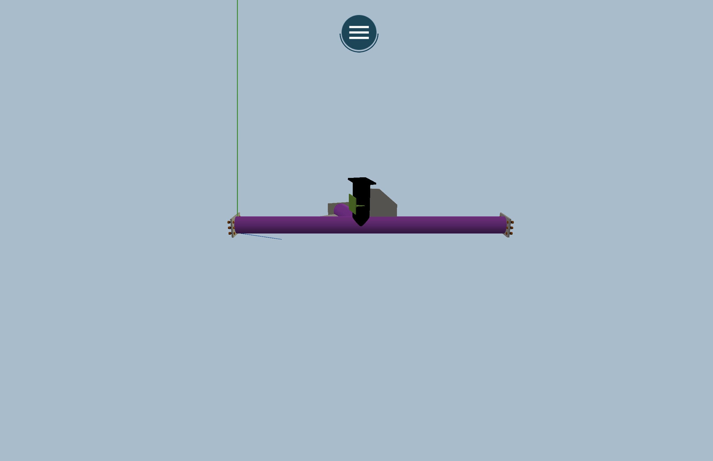
Access 3D viewer
Not sure if you selected a correct mode? Check our Choosing a Path: Fabricate, Inspect, or View? article for more details.
3D overview
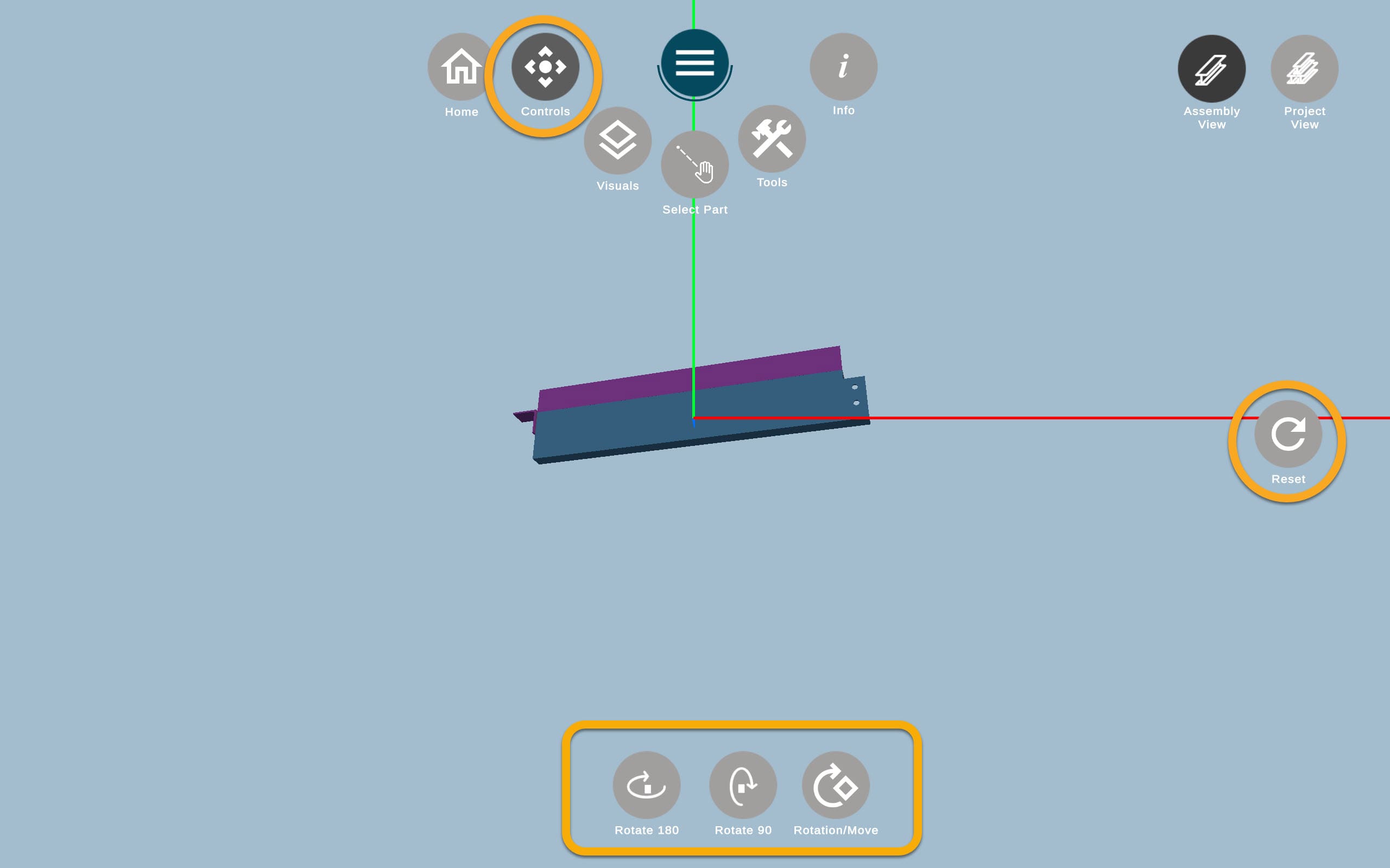
3D viewer has a variety of options designed to cover all need that might occur working with the assembly. Here is the overview of the buttons: from left to right

![]() Home button directs a user to the Mode view (Fabricate, Inspect, View).
Home button directs a user to the Mode view (Fabricate, Inspect, View).
![]() Controls allows moving the assembly and view it from different angles.
Controls allows moving the assembly and view it from different angles.
![]() Hamburger button hides all other buttons to clear the view.
Hamburger button hides all other buttons to clear the view.
![]() Visuals are designed to easily distinguish different parts of the assembly.
Visuals are designed to easily distinguish different parts of the assembly.
![]() Select part helps to change the main part of the assembly from a default one for alignment.
Select part helps to change the main part of the assembly from a default one for alignment.
![]() Tools has 2 options to measure an assembly and check the name of the assembly parts.
Tools has 2 options to measure an assembly and check the name of the assembly parts.
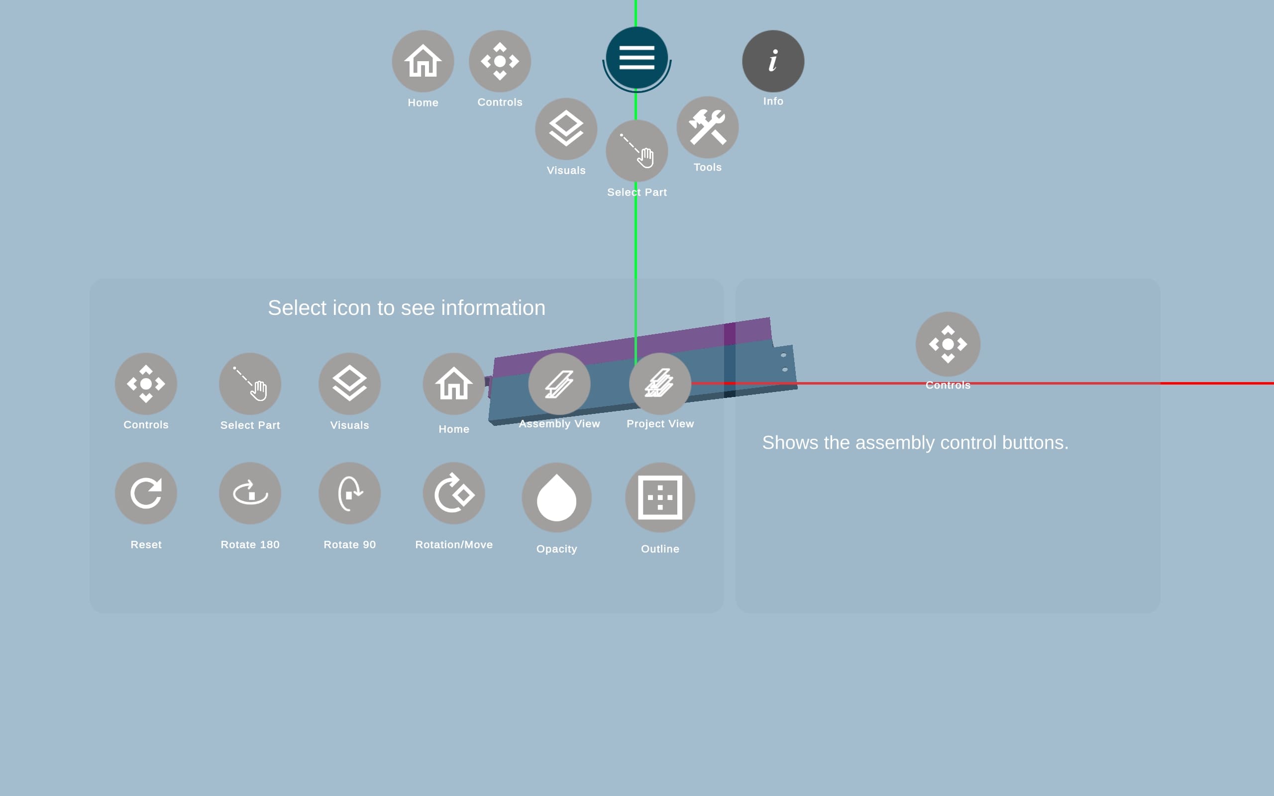
![]() Info button serves as a guide to all other features to remind their functionality.
Info button serves as a guide to all other features to remind their functionality.
![]() Assembly View shows only one assembly within the 3D viewer.
Assembly View shows only one assembly within the 3D viewer.
![]() Group View switches the view from a single assembly to the whole project.
Group View switches the view from a single assembly to the whole project.
All the other buttons are related to the Controls, as it’s a default view.
Controls
Controls are designed to allow you to view the assembly model from any angle. It consist of 5 main actions:
![]() Rotate 180 – allows changing model direction on 180 degrees horizontally.
Rotate 180 – allows changing model direction on 180 degrees horizontally.
![]() Rotate 90 – allows changing model direction on 90 degrees vertically.
Rotate 90 – allows changing model direction on 90 degrees vertically.
![]() Rotation/Move – changes the mode when you can either rotate or move the model with fingers.
Rotation/Move – changes the mode when you can either rotate or move the model with fingers.
![]() Reset – return model to its default position.
Reset – return model to its default position.
Zoom in and out model with fingers.
Visuals
Visuals can be helpful to divide a model by parts and see the connections between those parts.
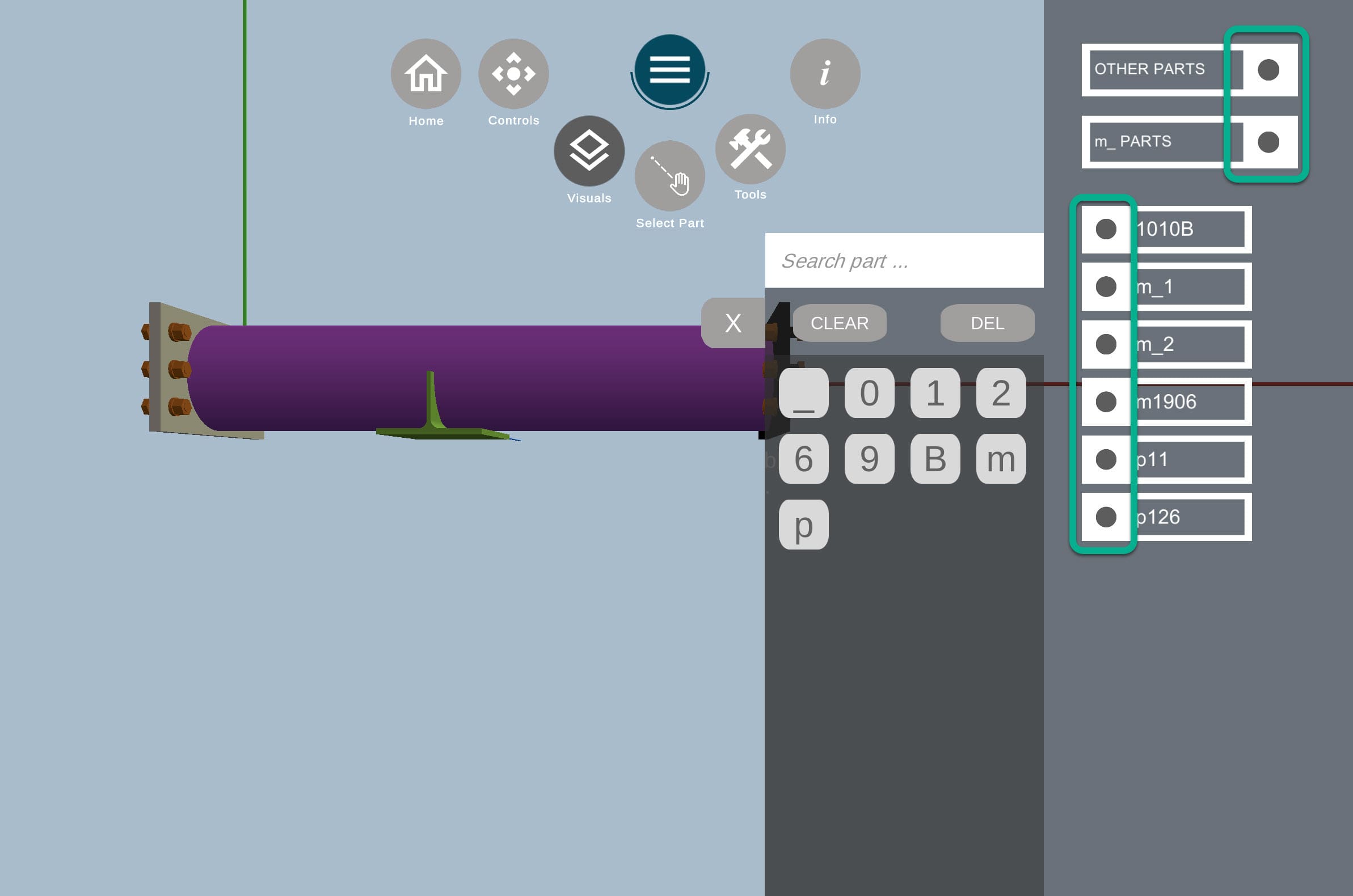
It’s possible to leave only main part with the button OTHER_PARTS.![]()
You can switch on and off the parts with the circles with part names on the left.
Dark gray circle – the part is visible (turned on).
Light gray circle – the part is invisible (turned off).
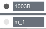
By clicking on the magnifier within the Visuals submenu, you can also open Search and look for specific parts only.
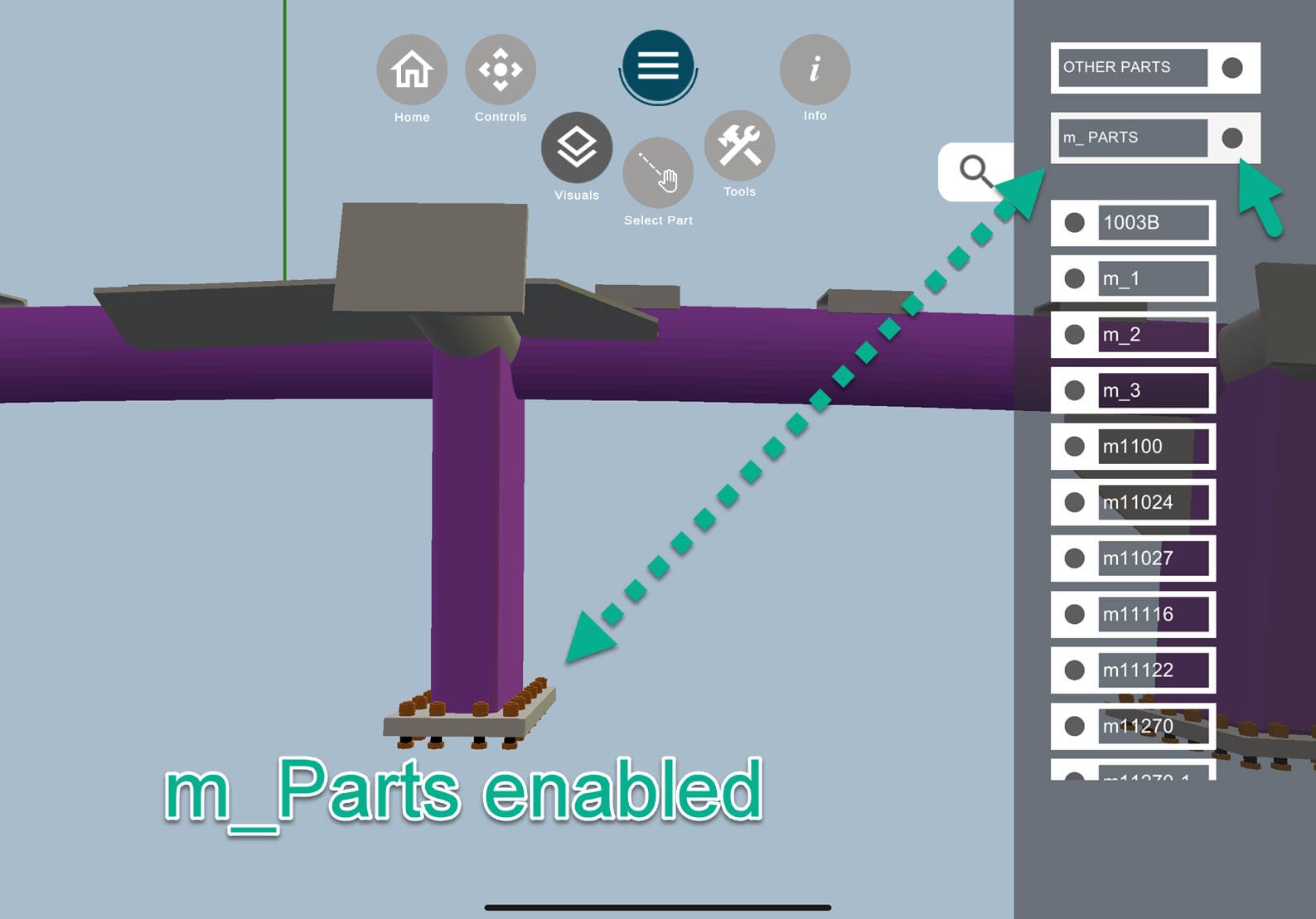
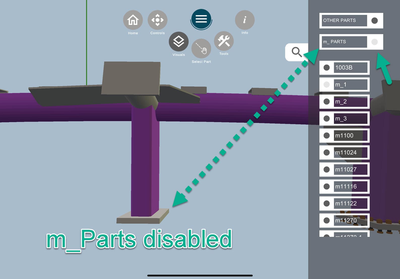
One of the useful features of the Visuals is m_PARTS, which stands for miscellaneous parts. It helps to remove such parts as bolts:
Select Part
Select Part is a tool that helps to change the part and model rotation for alignment.
Main part is the one that is used for alignment with the real assembly. The default main part is usually the biggest one within the assembly model, and it is always highlighted in blue, while the other parts do not have a designated color.
![]() Once you click on Select Part button, you will see a new submenu with Controls buttons. To change the main part, rotate/move the model as convenient and tap of the part you want to have as main.
Once you click on Select Part button, you will see a new submenu with Controls buttons. To change the main part, rotate/move the model as convenient and tap of the part you want to have as main.
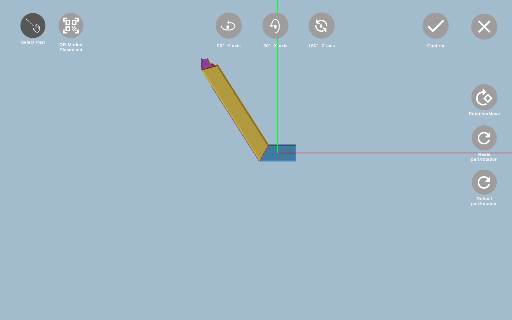
To learn more, click here and check Part Selector.
QR Marker Placement
QR Marker Placement is a tool that resides within Part Selector and is a part of its flow.
It was created to work with curved beams and odd shapes, so in most cases you will stick to the automatic QR Code alignment that is triggered after you confirm the main part position within the Select Part tool.
If automatic alignment result is not satisfying for you, you can always change the marker postion manually.
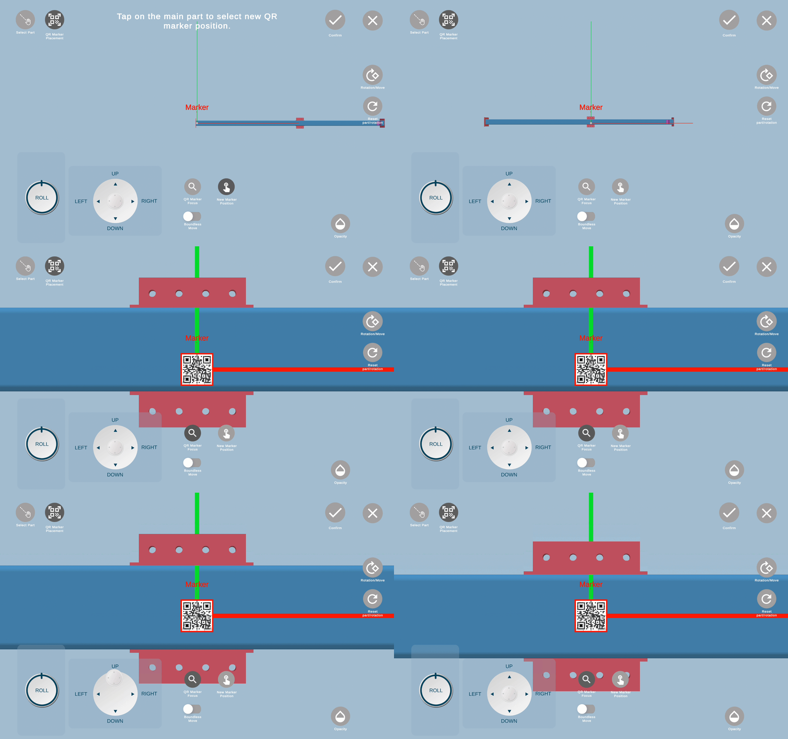
To learn more, click here and check QR Code Marker.
Tools
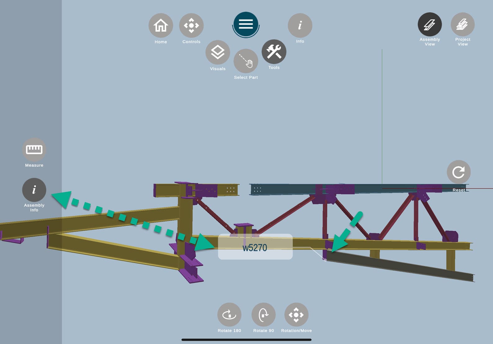
Tools submenu has 2 options: Measure and Assembly info.
![]() Measure is a useful tool for checking an assembly and determining the distance between certain points of the part/parts.
Measure is a useful tool for checking an assembly and determining the distance between certain points of the part/parts.
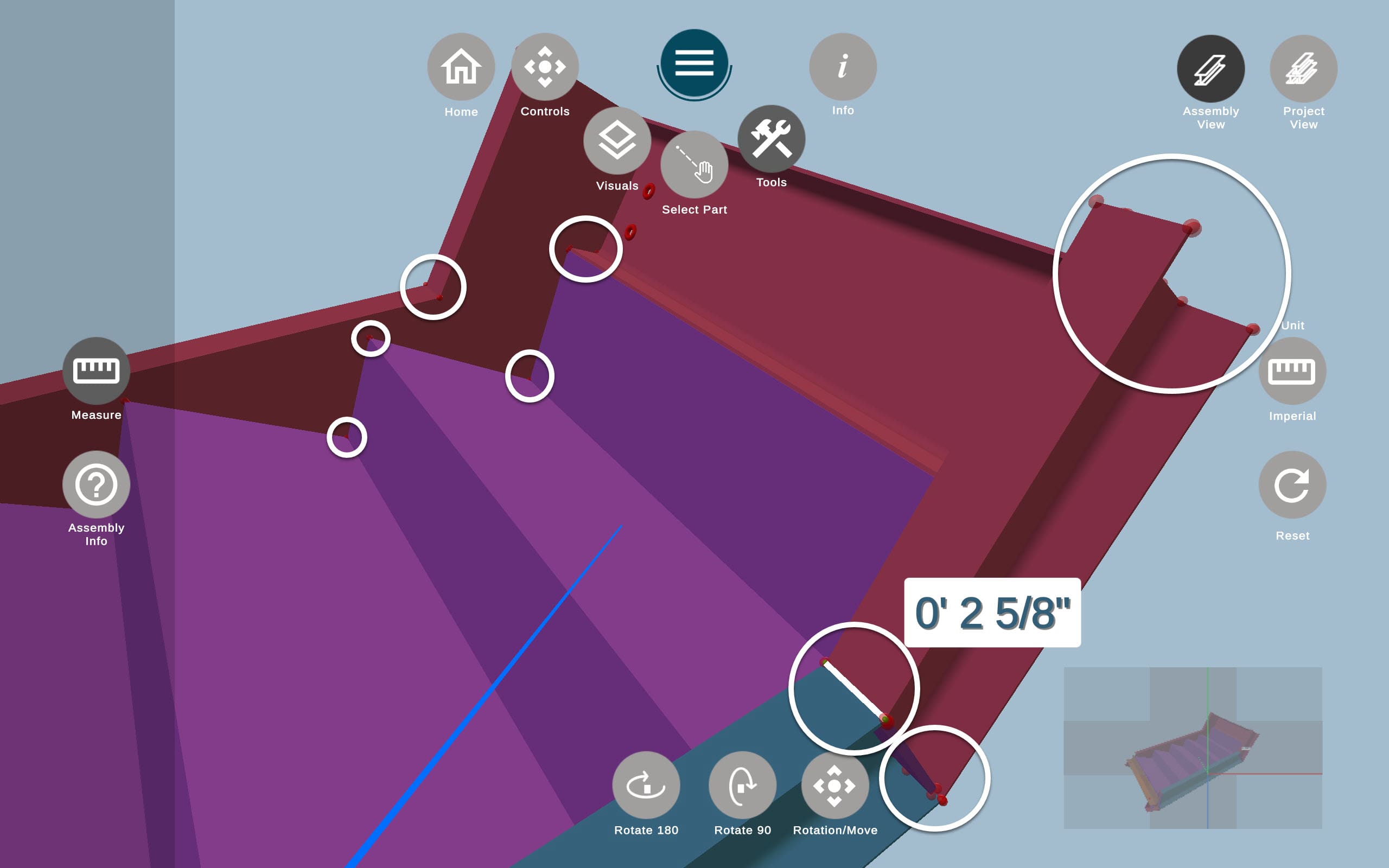
To measure the distance, zoom in an assembly and click on any two red dots between any parts.
For your convenience, we emphasized some of them with white circles on the screenshot:
Feel free to use visuals ![]() if you need to remove any parts for your convenience.
if you need to remove any parts for your convenience.
You can also switch between metric and imperial using the Unit button on the right.
It's only possible to measure the distance between two red dots.
![]() Assembly info should not be confused with Info
Assembly info should not be confused with Info ![]() button outside the Tools, as the only function of Assembly info is to display the part name.
button outside the Tools, as the only function of Assembly info is to display the part name.
After clicking on the button, it will turn dark gray. To view the name, simply click on any part of the assembly model within the 3D viewer.
The Assembly Info feature can be quite useful if you need to remove a certain part from the visuals ![]() but do not know the part name or need to quickly learn the name of the part for any informational purpose.
but do not know the part name or need to quickly learn the name of the part for any informational purpose.
Assembly/Project view
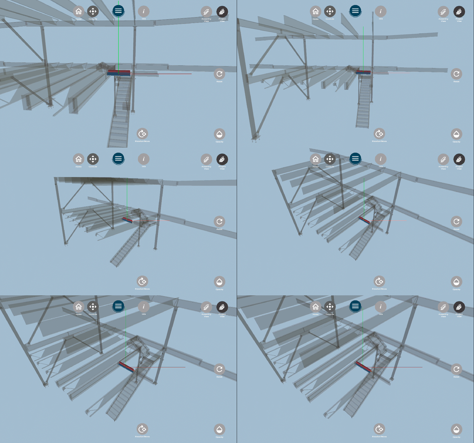
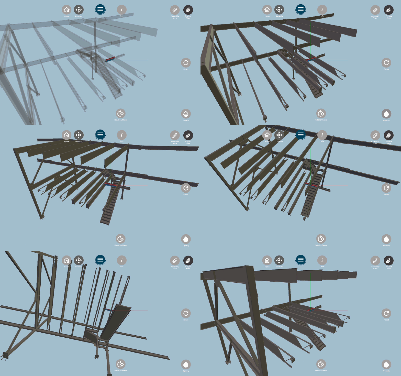
Assembly view is set by default. However, if you want to view the assembly with the project perspective, you can click on the Project view on the top right:
