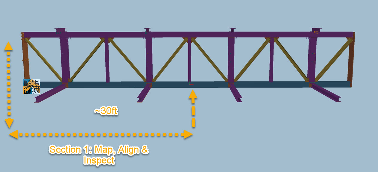
Once alignment is complete, inspect the section before moving on.
Moving to the Next Section
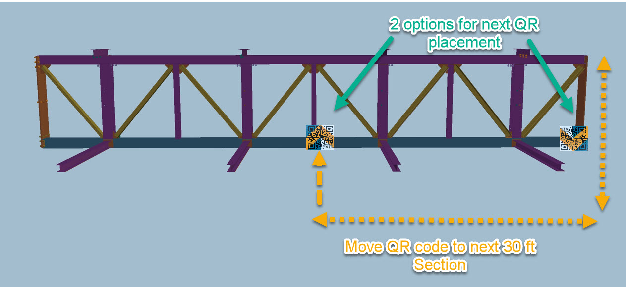
After completing the first section, the QR code must be repositioned to continue aligning the assembly.
Move the QR code to the next reference point along the assembly or if the assembly is 60ft or less move the QR code to the opposite end.
On the device:
Tablet > Tap Home
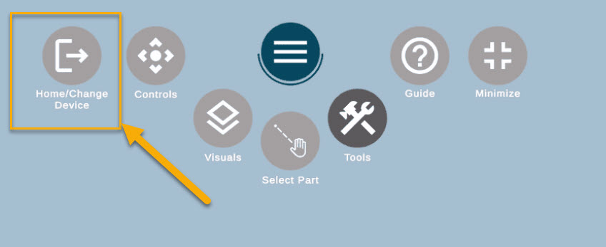
HoloLens > Select Home / Change Device
Once you return to the Part Selector screen:
Update the QR code location so it matches the new position on the assembly.
Confirm the QR placement screen.
Scan the QR code again from the new location
Next Section Alignment Process
After rescanning the QR code:
Map the next section of the assembly
Align the components as required
Inspect the section
This process can be repeated for the full length of the assembly, ensuring each section stays within the supported alignment range.
Aligning 4th side of Assemblies
If you are working with an assembly that is 30 ft or shorter, you can typically map, align, and inspect three sides of the assembly using the standard workflow.
To inspect the fourth side, the map must be cleared and recreated from the new position.
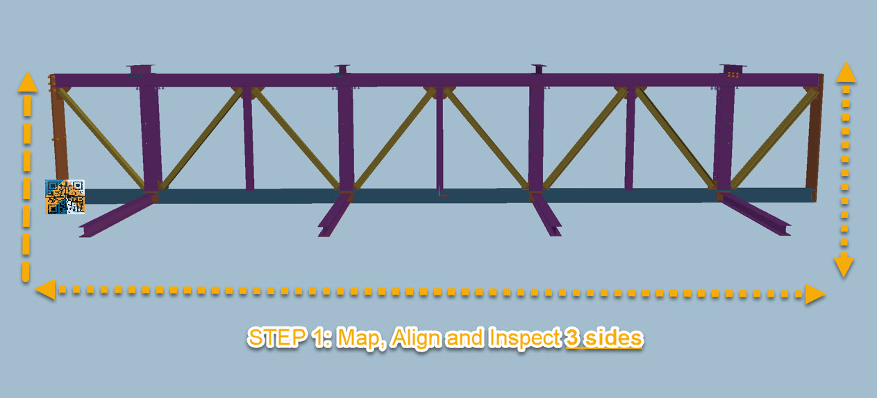
Step 1: Align & Inspect 3 sides
Inspect the first 3 sides as normal. Map, align and inspect.
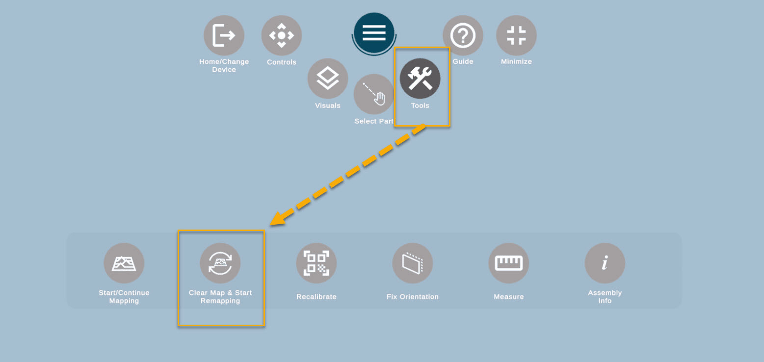
STEP 2: After completing the inspection of the first three sides, tap Tools.
Select Clear Map.
The system will immediately prompt you to start mapping again.
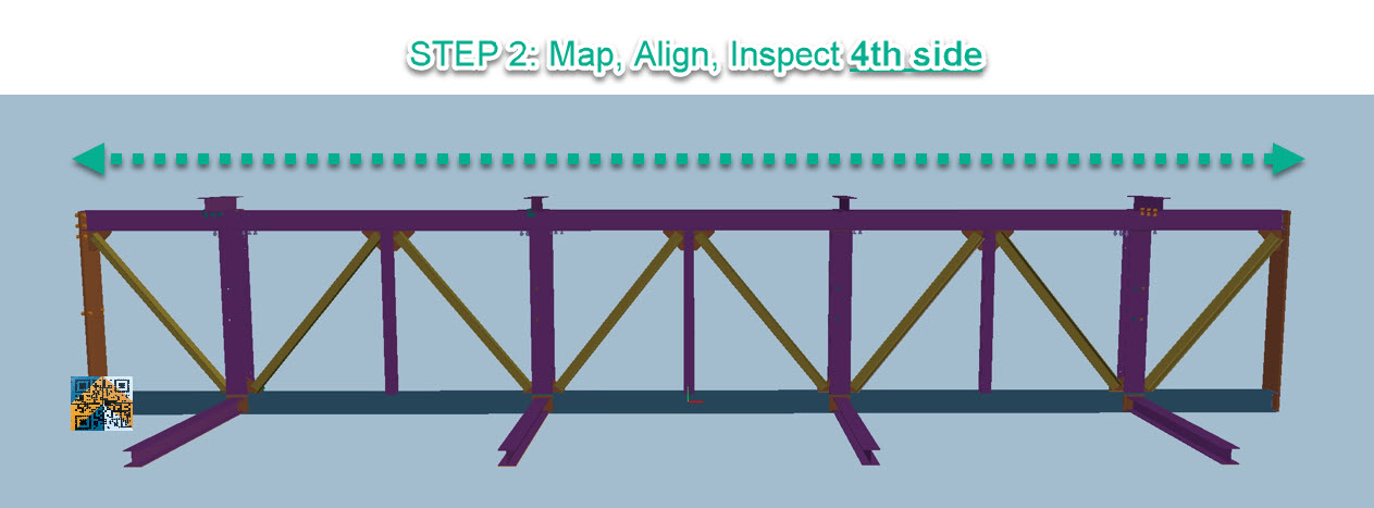
STEP 3: Begin mapping the fourth side of the assembly.
Because the hologram has already been aligned for the first 3 sides, the alignment should already be very close.
At this stage:
Perform a micro-alignment
Continue with the inspection process for the 4th side